CAT5 Wiring
When using CAT5 cable:
- Do not exceed a maximum of 18 feet (5.5 meters)
- Follow these pairing guidelines:
- One pair is dedicated to Gnd
- One pair is dedicated to +24V
- One pair is dedicated for Cresnet Y and Z
- Do not use one pair for Cresnet Y and one pair for Cresnet Z.
Legacy Crestron Product Pinout
When using legacy Crestron products, use this pinout:
| PIN # | SIGNAL | DESCRIPTION |
| 1 | +24V | Power (Network) |
| 2 | GND | Ground (Network) |
| 3 | C+ | Chrominance (Positive) |
| 4 | C- | Chrominance (Negative) |
| 5 | Y | Data (Network) |
| 6 | Z | Data (Network) |
| 7 | Y+ | Luminance (Positive)/Composite |
| 8 | Y- | Luminance (Negative)/Composite |
| 9 | GND | Ground (Network) |
| 10 | +24V | Power (Network) |
Power Calculation Table
The following table can be used to calculate power:
| Resistance | Wire Gauge |
| 13 | Doubled CAT5 |
| 8.7 | Tripled CAT5 |
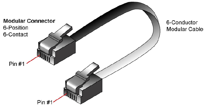
Modular Cable Requirements
If a 6-conductor modular cable is used to power Crestron devices, then it must be rated for 30VDC, 140º F (60º C) minimum. It must also be rated to carry sufficient current for loads. UL style 20251 cable can be used to carry up to 2 Amps when used in a dual power and dual ground configuration as shown below:
| From Pin | Description | To Pin |
| 1 | +24V | 1 |
| 2 | +24V | 2 |
| 3 | Y | 3 |
| 4 | Z | 4 |
| 5 | GND | 5 |
| 6 | GND | 6 |